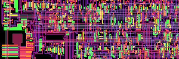
The Visual 6502 is a project run by Greg James and a handful of self confessed microchip archaeologists. By meticulously taking hundreds of photographs of microchips they then stitch them back together and convert all of the die information into a vector format for future preservation. Greg explains the reasoning behind this mammoth process in the site FAQ:
“There are many excellent emulators available, but emulation is approximation. It can be extremely difficult to create an accurate emulator, because the typical approach to writing an emulator is to glean information from chip specification documents or more rarely from any chip schematics that happen to be available. This information is always incomplete and even the original chip logic schematics (also Verilog and VHDL code) can differ from what was actually built in silicon (see ECO). A disciplined emulator will capture and use traces of actual chip behavior, but it’s near impossible to capture the billions of sequences of bits that a real chip gives rise to. Instead, we build a virtual chip by modeling and simulating the actual microscopic parts of a physical chip. We’re interested in accurately preserving historic designs.”
Taking the data compiled by their process the web site offers a visual chip to play with. At present they have the 6502 online, made famous in just about every early home computing device such as the Atari 2600. There is also a 6800 to play with. The simulator works by showing the assembly code running down the right-hand side and a complete visual chip layout on the left. As the code runs you can literally watch the instructions fire across the chip – zooming in and out and watching the transistors propagate the messages. You’d be forgiven for wondering how accurate a JavaScript simulation could be – Greg explains:
“The simulator is running an idealized “digital” circuit based on our model of the chip’s network of transistors and wires. It does not account for “analog” behavior (resistance, capacitance, leakage), has no propagation delays, and transistors switch on and off instantaneously. The real chip uses the same network of transistors (barring any mistakes we may have made in our model), but these transistors are analog devices. Our simulation uses a few simple heuristics to account for the differences in behavior between the actual analog circuits and our idealized digital model. In our simulation, if a transient short occurs from power to ground, ground wins. This may happen in our iterative solver as the simulation state is converging. Also, when two floating regions are switched together, their final voltage is taken from the region with the most components. This is a simple but completely non-physical way to account for capacitance.”
Even if like me you have no understanding of chip design, and your assembly coding skills haven’t been deployed in decades, this is still a remarkable and fascinating project well worth exploring.
